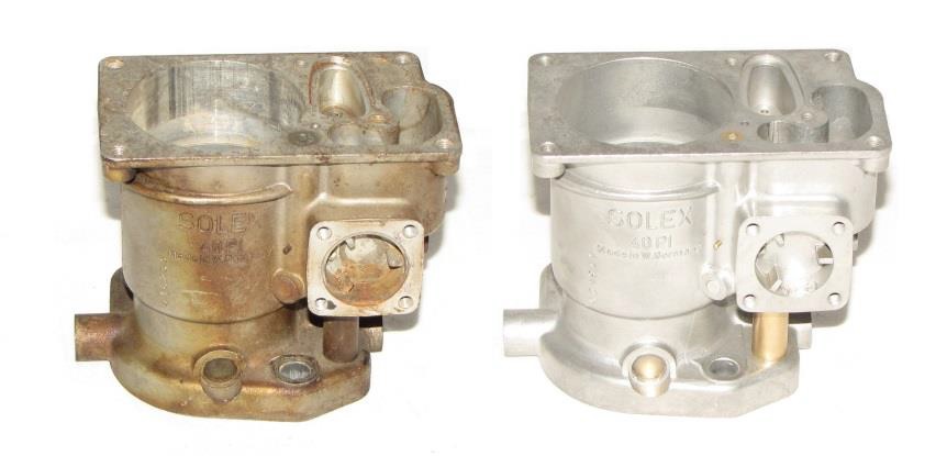
Restoring the Solex 40P-I spill tube carburetors
The first article on the 911 carburetor provided a general overview of the different carburetors used in the 911 and ways to deal with common problems. The next three articles will focus on repairing and restoring individual carburetor types. Beginning with first carburation system to be used on the Porsche 911 series, the Solex 40P-I.
The Solex 40P-I was at the time a completely new way of delivering fuel to the engine. Usually a carburetor has its immediate fuel supply in the fuel bowl located inside the carburetor itself. The problem with this is fluctuations in the fuel level due to acceleration, deceleration, and cornering can cause less than ideal fuel mixtures, as the height of the fuel level in the bowl will effect CO levels. Solex tried to eliminate these issues with the spill tube carburetor.
The spill tube system allowed for the fuel bowl to act as both the fuel supply as well as an overflow reservoir for the carburetor. The fuel bowl was mounted in the intake manifold and was fed fuel from the gas tank via an electrical fuel pump. Fuel was then circulated through the carburetors via a mechanical fuel pump mounted on the front of the engine and driven off the 1-3 bank camshaft. The mechanical fuel pump contains two pumps, one for each bank of carburetors. By circulating the fuel through the carburetors, Solex was able to maintain the desirable amount of fuel directly around
the jet pack while allowing un-needed fuel to drain back to the fuel bowl. By maintaining a steady supply of fuel around the jet pack and returning un-needed fuel volume away from the jet pack meant that the effects of acceleration, deceleration, cornering and altitude would be minimized.
The carburetors were also positioned directly above each respective intake runner on the engine providing for optimal air flow characteristics. Each carburetor was also individually tune-able for not only idle mixture control but air flow and accelerator pump discharge volumes. Though many of these significant features should have revolutionized the carburetor industry, I believe they were also the down fall of this short lived carburetor. The complicity of the fuel supply system can be challenging to diagnosis as you effectively have three fuel pumps in the car. The large amount of adjustments available on the carburetors though desirable to be able to perfectly tune the engine , also mean more moving parts to wear and lose their adjustments. The throttle linkage system is also quite complex with many moving parts and adjustments needed to really make the car perform well.
In the current atmosphere of restorations we are seeing more and more Solex carburetor sets being restored. Whether currently installed or in storage there is just no getting around the fact they are 47-49 years old and most have seen a lot of miles by now. Typically the repair time and cost to repair these carburetors is much more than other carburetor systems used on the 911. Unlike the Weber or Zenith carburetors the intake manifold and linkage system have to be considered part of the carburetor overhaul as well as the recirculation pump.
When restoring a set of Solex 40P-I carburetors start by removing the complete assemblies from the vehicle and setting them on the work bench. Make sure to use a bench that has plenty of space as there are a lot of parts in these carburetors.
When dis-assembling the carburetors you should be looking for signs of wear and damage as you go, most of these carburetor sets will need a lot more than just a gasket set and quick clean. As you dis-assemble each set lay out the parts in the order in which they came off, it will help you both with re-assembly as well as cleaning and checking all of the parts.
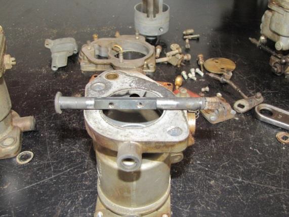
Starting with the linkage system look for play in the cross bar and individual linkage rods, these are usually the first things to be removed when dis-assembling the carburetors. Take a good look at the pivot ball areas on the transfer rod. On almost every set I find that the ball wears into the socket of the rod. This allows the rod to move sideways when it should just rotate and begin to open throttles on the carburetors. This will play havoc when tuning as you can usually make the engine idle smoothly yet with a light throttle the engine will be rough due to imbalance in the air flow through all six carburetors. If the shaft and ball do show signs of wear put them off to the side and continue disassembly.
With the linkages removed next remove the top air filter adaptor plate and the fuel inlet line that is connected to each carburetor. Un-bolt each carburetor and lay them out on the bench. Disassembling each individual carburetor is pretty
simple, start by removing the four top cover screws then pulling off the top cover. The jet carrier is held in with two captive screws which once loosened will give you something to hang on to remove the jet carrier. With the jet carrier out you want to go ahead and remove the jets so you can pin fit to verify size as well as clean the jets and carrier. Pin fitting jets is a must when rebuilding any carburetor; about 50% of the jets we see have been drilled and are not the size they are stamped with. I have also seen jets installed in carburetor sets that are all stamped the same size but when measured are all different sizes, which really makes it hard to pinpoint weird drivability problems later.
Next, disassemble the accelerator pump system by driving out the pivot pin on the pump cover housing. It is easier to do this while it is still attached to the carburetor body. You want to take a good look at the pin as it is another area that usually wears out. When the pump arm wears a groove in the pivot pin it delays the action of the fuel pump which
in turn can result in a stumble off idle due to the delay in fuel being injected. You should also have a good look at the linkage rod that comes off the throttle lever. Look for wear where the rod goes thru the pump arm, often the rod can be half its original diameter due to wear and tear. Next remove the pump cover and diaphragm and spring and set off the side; you will clean and flatten the pump cover later. To remove the fuel pump rod from the throttle lever you will need to remove the throttle lever from the throttle shaft as the pump rod is screwed into the lever.
The only part left in the carburetor body now is the throttle plate and shaft. Before pulling the throttle plate out you can check the throttle plate and housing wear by lightly closing the throttle plate against the bore and then using a flash light under the throttle plate you will be able to see any worn areas easily. The areas that wear the most are where
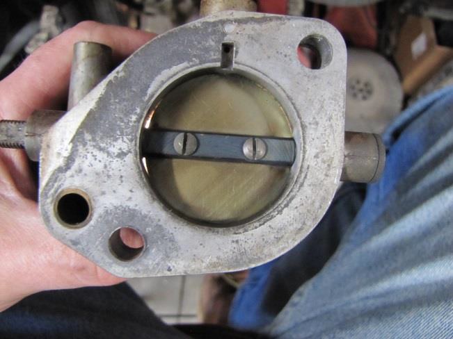
the throttle plate and shaft meet the carburetor body, the wear here happens as the brass throttle plate rubs against the soft zinc alloy body. Through the throttle plate will never be a completely light free seal excessive wear must be corrected by over boring the throttle bore and installing a new oversize throttle. Unmetered air that is allowed to bypass the throttle will cause the engine to idle to high as you will not be able adjust the airflow correctly. In the worst case we have seen the throttle plate bent, in an attempt to reduce the air flow the throttle is adjusted closed to the point where it impacts on the throttle bore opposite the throttle shaft. The effect of this is the plate may bend making the problem worse, or if it does not bend it then wears into the progression port area.
Lastly we want to look at the throttle shaft, before removing the shaft gently rock the shaft up and down and feel for any excessive play in the shaft. Solex used a combination of bronze and Teflon bushings, generally the effect I have seen is that the Teflon will wear out and the bronze bushing will then tend to wear into the throttle shaft. Depending on how many miles the carburetor set has done the throttle shafts may need to be replaced along with the throttle bushings. Normally I will remove the throttle bushings and install a full length bronze bushing as it seems to last longer and supports the throttle better. Check the throttle shafts for excessive wear. If the shaft has a lot of heavy grooving I would replace it. If the wear is light and it can be polished up then go ahead and re-use it. As a general rule I will go ahead and replace the shaft when it measures 7.94m/m or less from its original size of 8m/m.
With all the individual carburetors dis-assembled everything needs to cleaned and prepped for final inspection. Worn throttle bushings need to be replaced and sized to the throttle shafts, worn throttles need to be bored and new throttle plates made, all the gasket surfaces need to be checked for surface distortion and then corrected if needed.
Re-assembly of the individual carburetors is fairly simple; basically it is the reverse of the dis-assembly process. Starting with the throttle shaft lightly lube it and install into the carburetor body installing the throttle lever and pump shaft assembly. Check the throttle shaft end float and shim it to remove excessive travel. Be careful not the shim it too tightly as the shaft may bind in the body when it gets hot as the zinc alloy carburetor has a different expansion rate than the steel throttle shaft. Install the throttle plate check that it does not bind when it closes and that it has a nice even seal around the throttle bore. Assemble the accelerator pump diaphragm, spring and cover back onto the carburetor body and then install the pump arm and pivot. Start the adjusting nut on to the pump rod but leave the lock nut loose as you will need to set the delivery volumes later. Assemble the sized main and idle jets in to the jet carrier, install the new gasket and O-ring and install the completed assembly back into the carburetor body being careful not to damage the gasket or the O-ring. Assemble the top cover and the auxiliary booster into the carburetor body and then set it off to the side until the rest of the carburetors are assembled.
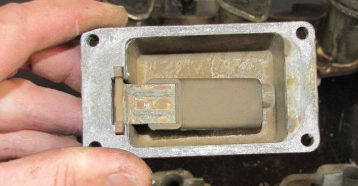
Before installing the carburetors on to the intake manifold the fuel bowl needs to be removed for cleaning and checking of the float as well as fuel passages. The gasket surfaces for both the carburetor sealing flanges and intake to cylinder head surfaces need also to checked for any surface distortion and corrected if needed. The drain back bores should also be checked and blown thru to insure that there are no obstructions that could stop fuel returning from the carburetor to the fuel bowl. Once the manifold has been cleaned and inspected and all of the sealing surfaces checked assemble a new needle valve and install the float and float bowl.
With the intake manifold clean and the float bowl installed the individual carburetors can be reinstalled on to the manifold. To assemble the linkages first install the cross bar and adjust the preload on the ball pivots so that there is no end float yet not so tight that the throttle will feel stiff or bind. Previously I spoke about the wear that occurs in cross bar, if yours is worn it will need to be repaired or replaced before trying to install and set up the throttles. With the cross bar installed and the return spring hooked up so that it holds the idle stop screw against its stop install the first connecting rod onto the crossbar and then carefully snap the other end onto the throttle lever of the first carburetor. Using a flash light to look down the carburetor screw the connecting rod in or out until the throttle is in the closed position. Install the next rod onto the next carburetor and repaeat, don’t worry if it is not perfect at this point as once the carburetors are back onto the engine the fine balance will be set then.
Once all the throttles have been adjusted and the fuel lines have been installed the next item that should be set up on the bench is a check of the float level and to adjust the accelerator pump delivey volumes for each carburetor. To do this operation on the bench is a little tricky as you will need two fuel pumps, one to supply fuel to the fuel bowl and then one to circulate the fuel through the carburetors. To check the fuel bowl setting connect a piece of clear plastic hose to the bottom outlet fitting on the fuel bowl, bend the hose up and hold it so that the fuel wont run out and then turn on your supply pump. Make sure that the supply pump cannot exceed 2.5PSI otherwise the float height will be incorrect. Looking at the clear pipe the fuel level should be between 15m/m and 20m/m down from the top of the fuel bowl. To adjust the float level up or down change the sealing washer thickness under the needle valve.
To set the accelerator pump dischacharge volumes you will need two fuel pumps, the first pump to supply fuel to the fuel bowl and a second pump to circulate fuel through the carburetors. Once again make sure the pumps don’t exceed 2.5PSI. With both pumps running activate the throttle arms and measure the discharge volume from each accelerator pump nozle. The discharge should be between .40cc to .65cc depending on the season and your specific area. To adjust the discharge volumes turn the adjusting nut on the accelerator pump rod and then tighten the lock nut down to retain the adjustment.
After setting everything the carburetor assemblies are ready to install onto the engine. Make sure that the cylinder head gasket surfaces are clean and use a new base gasket gasket, make sure that the ignition system is in perfect operating condition and the fuel in the gas tank and lines is fresh. Start the engine and warm the vehicle up, it may run a little rough during this stage. Once the engine is up to temperture raise the engine speed to 1200-1400RPM and check the balance on each individual carburetor body, adjusting the throttle position to match the airflows perfectly. After sychonising each bank let the engine come back to idle and balance side to side using the idle stop screws on the cross linkage. With the throttles balanced now check and adjust the mixture screw on each carburetor until the engine is its smoothest, you may have to lower the idle speed so just make sure to adjust both sides evenly to maintain the same airflows through each bank. Finally switch off the engine and install the remaining linkages to complete the installation, be sure to check that each ball socket is lube and has no play in the joint. Also make sure to check and adjust the full throttle stops making sure that the throttle plates are opening completely and not going over center in the throttle bore.
Install the air filter assembly and time to roadtest ……..
Written By Kurt Donohoe
www.partsklassik.com